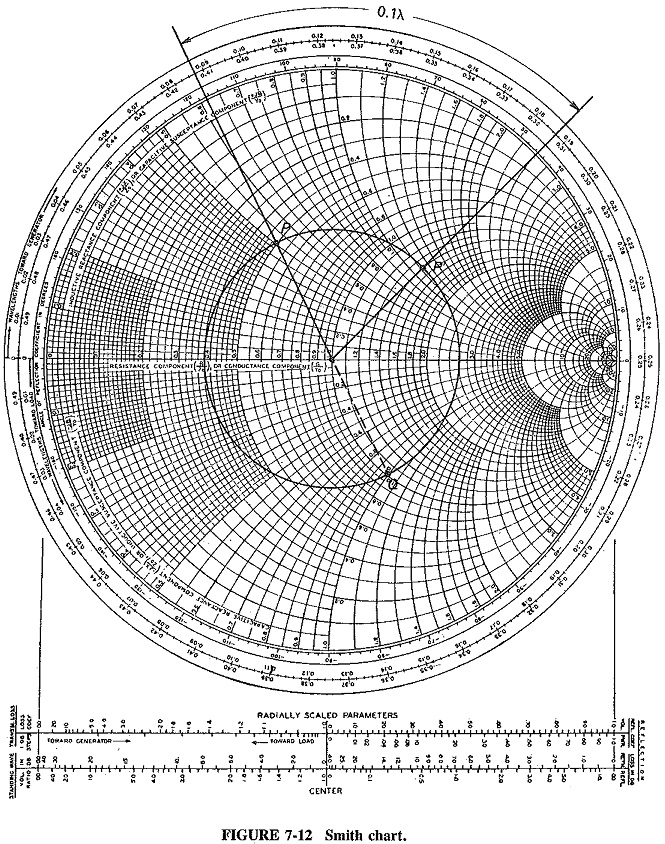

The Smith Chart is drawn by superimposing these two types of circles. The circles with centers at and radii = 1/(r+1) are known as constant resistance circles as shown in following fig.The circles with centers at (1, 1/x) and radii = 1/x are known as constant reactance circles as shown in following fig. (b) What is the imp edance at 0: 1 Since w e an t to mo v a y from the load (i.e., ard. (a) Lo cate z L Z L Z 0 0: 1+ j 0 5on the Smith c hart. Separating the real and imaginary part, we getįurher simplifying the above two equations, we can re-write them in standard circle equation form asĢ + (v - 0)2 = 2 with center at and radius = 1/(r+1) and The 0: 1 length line sho wn has ac haracteristic imp edance of 50 and is terminated with a load imp edance of Z L 5 + j 25. Therefore, the possible values of Γ will remain within the unit circle. Γ = u + jv = Rejθ, where R is the radius and θ is the angle of incidence.įrom the last two equation, we can see that there is one-to-one correspondence and for every Z we can obtain a unique Γ. The above equation can also be written as Γ = / for r lies between 0 and ∞, x lies between -∞ and +∞. Γ = (ZL-1) / (ZL+1) as Zo takes constant values such as 50Ω, 100Ω, etc. Therefore, Reflection coefficient can expressed as Normalized impedance, Z = ZL/ Zo = r+ jx, where r = R / Z0 and x = X / Z0. This is because the behavior of the transmission line depends on load impedance as well as characteristic impedance. Normalized impedance is used for plotting on Smith chart. Γ = (ZL - Zo) / ( ZL + Zo ) where, ZL is load impedance and Zo is the characteristic impedance of transmission line, a constant. Therefore, from the fig., gamma can be expressed as, The amount of reflected wave depends upon the mismatching of the source and load impedances. The ratio of the voltage of reflected wave and the voltage of incident wave is known as the reflection coefficient. If there is impedance mismatching, part of the energy in the incident wave is reflected back giving rise to a standing wave. transmitter to antenna or antenna to receiver), the impedance of source must be equal to the impedance of load. While transferring the RF waves on a finite transmission line, for maximum power transfer from source to load (i.e. These are the impedance matching circuits. Transmission lines are the circuits that deliver power from a transmitter to an antenna and from an antenna to a receiver.

Although such a graphical procedure, nowadays known as the Smith chart, was developed in the 1930s prior to the computer age, it has retained its popularity and can be found in every data book describing passive and active high-frequency components and systems. His approach permits an easy and intuitive display of the reflection coefficient as well as the complex impedance in a single graph. Smith developed an ingenious graphical procedure based on conformal mapping principles. To show how the impedance can be converted into a reflection coefficient and vice versa, P. Frequently, the impedance is replaced by the reflection coefficient, a more convenient way to quantify the transmitted and reflected voltage-current waves. Changes in the length or operating frequency of these transmission lines result in periodic impedance behaviors not encountered in low-frequency circuits. Copper traces on printed circuit boards, coaxial cables, and even simple wires become transmission lines. At high-frequency circuit operation, voltages and currents behave like traveling waves propagating over finite-length components.


 0 kommentar(er)
